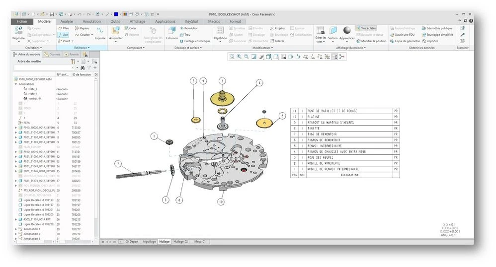
It is regarding the table functionality to be available in the 3d Part / Assembly Mode. I had a posted my comments a year back but trying to follow up to understand if we are really considering this scenarios and do we have a timeline defined for this functionality to be available for everyone to use
Not having this functionality is a show stopper for the MBD/MBE (Digital thread across the organization)
Having a simple table will also help
When I was typing my requirements in the comment I could see table functionality are available for this post too and not available in Creo
It will be good have a simple table like this
GENERAL MBD TABLE PLATFORM
-- Choosing where new tables should be created -- Resizing table columns or rows to content -- Adding semantics from table rows to model geometry ability to add -- Manually supporting movement or updating movement of table -- One click update of table contents (where the contents are not parameter based)
-- Able to add rows and columns for the table -- Adding Text Note in the Cell -- TABLES CREATED WITH TEMPLATE -- Copy paste table from one combination state to other combination state
TABLE TYPE: REVISION HISTORY TABLE 1 Inserting Symbols in the Cells - Merging of cells of the table - Merge Rows - Merge Columns
Auto BOM ballooning to the parts in the assemblies after generating the table
Good Have
- Auto BOM ballooning to the parts in the assemblies after generating the table
- Parameters for the Parts - Parametric BOM table for assemblies - Assign parameters to the Cells and Populate Cell Information
- Adding Windchill link of the part to track the revision and updates
- Adding link of Specification Documents in the part chart (Specification Present in Windchill)
I have one comments about the request to be able to add semantics from the table to model geometry (surfaces): The way I see this, table is not defined as an annotation that carries semantic info like geometrical tolerance or a dimension. as a matter of fact there are also no specifications about tables in MBD in the detailing standards. The standards describes tables only for drawings.
I believe that tables are essentially a container of information that organizes the data in a tabular form. This means that the rows/columns themselves are not the one that needs to be assigned with semantic references.
I believe that the main requirement/use case here is for someone to be able to highlight some geometry/surfaces/other annotations when selecting a specific table row/column/cell in the table. This is mostly a use case for human consumption of the data. at least for now.
Please confirm my understanding
As it goes for the timing for introducing tables for MBD, this enhancement is indeed being considered for implementation.
At this point in time I cannot provide a hard commitment for a specific release, however I can say that I hope to be able to introduce it in the short term. It will not be included in Creo 10, but possibly in one of the follow-up releases
In my experience the use case for tables is different than your example of "...highlight some geometry/surfaces/other annotations when selecting a specific table row/column...". Our primary use case is when tackling an MBD TDP where we need to detail wiring harnesses, piping, and similar which are normally handled within a drawing table. This cannot be done with current annotations. Additionally, we have seen TDPs with the requirement to present a BOM (not a model tree) in a presentation state.
Indeed there are many different kind of use cases for tables, my example above was just one of them.
Regarding your use case of wiring harnesses/piping etc. - may I assume that in this case you are currently doing that using repeat regions (instead of manual tables)?
Please include detailed documentation such as screenshots, images or video.
1. What product and version are you running? Creo Parametric 9.0
2. What is the problem?
As for 2D drawings you might want to add a table in a view but that only possible through a symbol which is time consuming to set up
3. Are you using a workaround? If yes, please describe it. Create a symbol for each table needed
4. What is the use case for your organization? Describe how your idea would work in context or how it would apply to a practical situation.
In the active combined state just click to add a table - define it as in 2D and place it
5. What impact does this problem currently have on your organization? (Number of users affected, hours of lost productivity, etc.) Make the work on 3d drawings more effecient
However, you give the bare minimum of information. The more details and context you give to document your idea, the better. Think about ways to educate and convince other Community members to support your idea and present your case to the product management team for consideration.
Additionally, I invite you to check out this topic where PTC executives explain product managers' approach to customer ideas and input for product roadmaps.
Sorry for the late reply, was away from this for a while. Adding my comments in Blue
I have one comment about the request to be able to add semantics from the table to model geometry (surfaces): The way I see this, table is not defined as an annotation that carries semantic info like geometrical tolerance or a dimension. as a matter of fact there are also no specifications about tables in MBD in the detailing standards. The standards describe tables only for drawings.--
Agree with your point but the Manufacturing team who operates on the shop floor needs to consume the information to manufacture a part.
Having a Semantic table will always be a value add which will help to analyze the part or assembly very easily and review meeting will be very easy using PTC tools like Creo View and Creo Parametric
I believe that tables are essentially a container of information that organizes the data in a tabular form. --- >
Hundred percent right and also provides the Product manufacturing information with links to the Standards and Specifications .
Information about the parent and child parts like
Raw Part and its different colors (Colors can be 10 to 20 also . So table is needed to add all this information on a MBD part )
Raw part with Specification, - Material , Colour, etc
MBD Assembly - If Table is provided in assembly mode - Balloons can be generated which Quality and Supplier vendors can see that information
This means that the rows/columns themselves are not the one that needs to be assigned with semantic references.
I believe that the main requirement/use case here is for someone to be able to highlight some geometry/surfaces/other annotations when selecting a specific table row/column/cell in the table. This is mostly a use case for human consumption of the data. at least for now.
Please confirm my understanding ----- >
Consumption of Data is important inhouse or when it is sent to suppliers.
Revision Table to track what has changed in the present revision and earlier release is important for the people who are working on the shop floor
Teams like Buyers, Manufacturing Quality , Tooling etc. When they export Creo Parametric data into creo view they will need see all this information to consume the MBD data and manufacture a part on the shop floor
Highlight the surface or geometry will be too good and you will save huge manual efforts and Users will be happy to use PTC products extensively
As it goes for the timing for introducing tables for MBD, this enhancement is indeed being considered for implementation.---
We are waiting for this functionality to be implemented as this become a show stopper in our organisation for MBD
At this point in time I cannot provide a hard commitment for a specific release, however I can say that I hope to be able to introduce it in the short term. It will not be included in Creo 10, but possibly in one of the follow-up releases
Michael we are moving to Creo 10 and we will be happy to have this functionally in upcoming version that will be helpful not for our organization but for all the organisation world wide. Looking forward to this