
Engineering & Butterflies
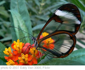 Today, I received a message from Greg Frankland, the same Greg Frankland who asked me to write about bananas. Well, looks like my first story was good enough to make him want read more.
In his message, he said “maybe this little guy will give you something to write about” and pointed me to a blog post about exotic butterflies: "The Incredible Glasswing Butterfly".
First of all, I had never heard of this species – have you? – and I must say I am pretty impressed with the beauty of this little thing.
In the article it reads:
“Transparency in nature is not something that has been very well understood. In order to achieve transparency the tissue must not absorb light. Neither can it scatter light, as this is the major obstacle to being see-through. …. The wings of the glasswing must, therefore, have the same refractive index all the way through them as otherwise this transparency could not possibly occur. It is thought (a postulation at the moment rather than sure fire fact) that the surface of the wing has a covering of protrusions that are so small they can be called submicroscopic. They have a single refractive index and so do not scatter light, so making the wings transparent.”
Many thanks to Greg for suggesting the topic. Transparency is a cool topic to discuss in an engineering context! We’ve created a little article when we reworked the rendering engine with the release of Creo Elements/Pro 5.0.
In this article we discussed a few best practices for rendering. The intention was to give the readers an introduction into what needs to be considered in terms of lighting, applying shadows, and global illumination. However, how does this relate to transparent objects?
Below are some of the best sections of that article, as I think this may be useful to those of you who are about to start dealing with renderings.
For the rendering experts among you, feel free to share your tips & tricks – or share some images with transparent components that you created!
Bettina
Four Best Practices for Photorealistic Renderings
While photorealistic rendering applications for engineers are not new, they are now more advanced and easy to use. Additionally, some are being integrated into standard CAD/CAM/CAE packages. This allows engineers to use their existing models seamlessly to create photorealistic images, rather than having to export models from their CAD/CAM/CAE system and import them into the rendering system.
As a result, more engineers have the opportunity to take advantage of these capabilities and their benefits. However, engineers with little experience with lighting, surfaces, and other aspects of photorealism will face a learning curve. Following four best practices—using imaged based lighting, appearance libraries, physically correct lighting and global illumination, and realistic shadows—can help engineers with all levels of experience with photorealistic rendering to more quickly and easily create highly realistic renderings.
Image-Based Lighting
One of the most difficult and time consuming aspects of rendering for those who are not lighting experts is positioning the lighting in a realistic manner, which can be a highly iterative process. Image based lighting (IBL) takes the guesswork out of lighting for novices. Using IBL, the user wraps a high dynamic range (HDR) image around the model. HDR is an image format that is used for settings, such as rooms or courtyards, that include the correct lighting and color to generate the right reflections. The HDR image becomes the background for the model, eliminating the need for users to manually position light sources. By using an HDR image, novices can instantly take advantage of expert lighting for use in their renderings. Millions of HDR images are available for purchase or download.
Check Out an Appearance Library
Another time consuming aspect of creating a photorealistic image is building up the materials on the surface of the model so it has the right texture and light reflectance properties. For example, glass, stainless steel , wood or injection molded plastic all require a different set of appearance parameters that include reflection, glossiness, and color texture (e.g. wood grain). By selecting from a library of appearances and placing them on the model, engineers can quickly and easily ensure that their models have the right surface properties every time.
Physically Correct Lighting and Global Illumination
Advanced users who want to set up their own lighting for their renderings can gain a better understanding of the impact of lighting on the model by using physically correct lighting and global illumination. Physically correct lighting includes two pre-set characteristics for every light used in the image: Intensity, which is represented by lux or wattage, and the color temperature of the light, which is the color the light gives off. For example, incandescent light gives off a yellow light while florescent gives off a blue light. Physically correct lighting applies the right intensity and color values when users select a lighting type, rather than requiring them to set these parameters manually. This allows users to set up lighting more quickly and increases accuracy by reducing the likelihood of errors. When the system uses standard terms for preset values(i.e. watts instead of lux), users will find it more intuitive and usability will improve.
Physically correct lighting should be used in conjunction with global illumination capabilities, which calculate the impact of both the light that comes directly from the light source and the indirect lighting that bounces off surfaces. Another aspect of global illumination is caustics, which show how light rays that are reflected or refracted by a curved surface or object appear on another surface. Together, physically correct lighting and global illumination enable engineers to see the full impact of illumination on the scene and on the model.
Realistic Shadows
Shadows have subtleties that, if rendered properly, make images look more realistic. First, shadows do not have hard edges. Users of photorealistic rendering software should remove any sharp edges from their models by using rounds and fillets.
Also, users should incorporate transparent shadows where appropriate. If a light shines on a solid object, the shadow will be grey. But if it falls on a transparent object, the shadow will pick up the color of the object the light is shining through. Using a transparent shadow capability in the software will incorporate the color of the transparent object in the shadow.