
Measure minimum bend radius
1. Describe the Problem
The minimum bend radius of cables and wires is entered into the Central Catalog in Creo Schematics (CS). When this transfers to Creo Parametric (CP) via XML, CP does a spectacular job of enforcing that minimum bend radius requirement. The CP behavior is to very obviously fail cables and wires that are bent tighter than the specification entered in CS. This is great! I don't need this to be changed.
Sometimes, our lead engineers need a measurement of the minimum bend radius of a particular routing. Meaning, even though the cables are routing successfully--well above the minimum bend radius specified in CS--measuring the minimum bend radius of the Cabling model is still a measurement we are obligated to deliver. At present, CP offers no tools for specifically measuring the bend radius of a given model; CP only offers tools to report the minimum bend radius of the wire and cable as specified in CP.
2. Are you using a workaround?
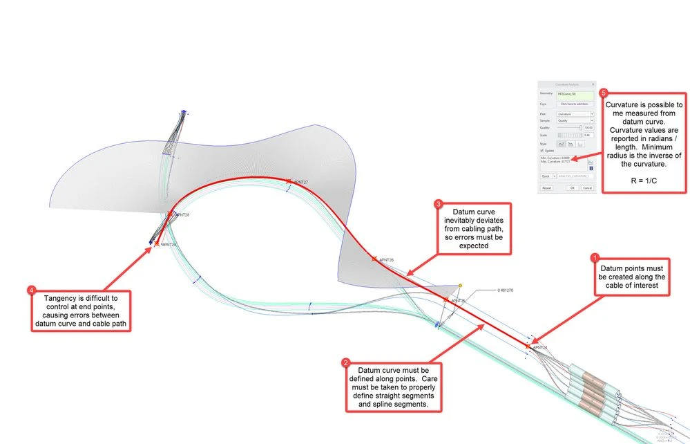
Per the image attached, it is possible to place datum points along Networks and coincident with Location Points. A datum curve can be constructed through those points, and a Curvature Analysis can be measured. The resulting curvature measurement can be reciprocated to calculate the bend radius values (i.e. radius = 1 / curvature). There are many problems with this technique. First, placing the datum points is tedious. Second, controlling the tangency of the datum curve requires creating extra points, which requires constructing additional datum features (e.g. CSYS features, to create offset points). Third, the datum curve does not follow the cabling paths correctly and thus introduces errors. A far better solution would simply be some kind of analysis feature or auto calculated parameter built into CP that would allow users to directly measure the minimum bend radius of wires and cables (and there may even be use cases for measuring Networks). At a minimum, even developing the Curvature Analysis tool to be able to measure Cabling features would be an incremental improvement.
3. What is the use case for your organization?
Use case is described in section 1.
4. What impact does this problem currently have on your organization?
An individual study using this workaround may only consume 15 minutes. But this requires the Design Engineer to specifically visually choose to study the area that looks tightest, and to visually choose the wire/cable that looks tightest. And only one measurement can be produced. This means the Design Engineer could overlook other areas which may be tighter. Requests for these measurements are currently not frequent. Possibly that is because the information is not needed frequently, or because these measurements are difficult to produce and therefore it is not a high enough priority to justify regularly performing the workaround described in section 2.