
MDB Annotation Dimensions should stay a set distance from Edge/Surface
1. Describe the Problem
We are interested in using Model Based Definition and putting our Annotations on our models for use in downstream processes in an effort to remove 2-D Drawings.
We make use of Family tables on our parts as they parametrically grow/shrink in size by a set distance for each instance.
When we place a dimension on our part to show the overall height or length of the part on the generic instance, the dimension is placed a distance from the edge that looks good, and works great in our combination state. In this case, our part is 4 Units High and 4 Units Wide.
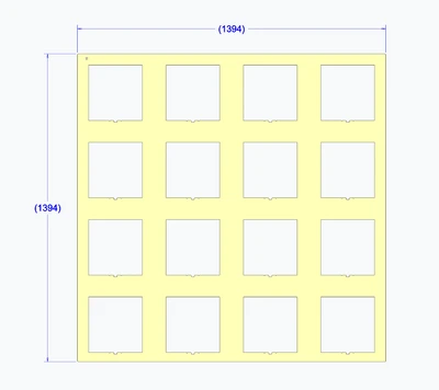
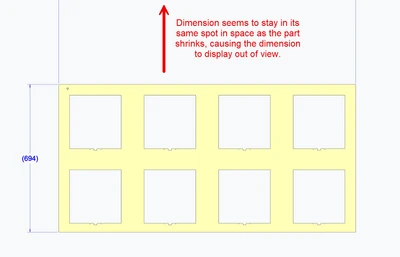
However, when we go to get the output for our next instance (in this case, a 2 Unit High by 4 Unit Wide option), the width dimension does not follow the edge distance (stays the same distance from the UCS it seems) and gets lost off the screen as the part shrinks.
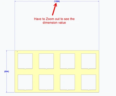
So, if we adjust our generic part to be a 2x4 Unit size, and dimension off of that size. Easy enough, right?
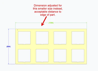
BUT when we go back to the 4x4 Unit size, now the dimension ends up within the part as the part grows, and overlaps with Geometry.
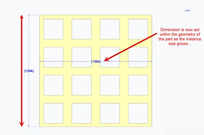
And now we go back and forth chasing this.
Ideally, if we set a dimension a distance from an edge on the model, can that distance remain constant no matter the size of the part? Is there a setting that can be applied for this?
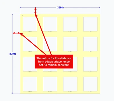
Again, this is a huge disruptor for our organization to help sell the benefits of MBD and moving forward with the new practices.
Please Vote this up!
2. Are you using a workaround?
None found other than accepting that dimensions will be accurate for only one size in the family.
3. What is the use case for your organization?
We want to make use of MBD/MBE in our organization, but this is a challenge in presentation to our downstream teams and doesn't help us sell the benefits of MDB. If they cannot read the dimensions that they need for inspection in our current processes, they will push back on moving forward with this. We are trying to replicate the same dimensioning schema that we would do in 2D drawings to help with the transition and not being able to do this on these part families is certainly causing some disruption.
4. What impact does this problem currently have on your organization?
Prevents us from fully moving to MBD into a drawing-less environment.