
Improve the calculated result of projected area to whole part
1. Describe the Problem
Creo Parametric provides an analysis feature "Measure: Area" to measure the area of a projected surface to an assembly. With the help of PTC support it was confirmed that this calculation deviates far more than the expected value of 0.15% as published here. We require a more accurate estimation of projected areas to meet our engineering needs.
The deviation is evident when using the Shadow Analysis feature, as demonstrated with a sequence of spheres: even at the highest accuracy settings, the projected area is not calculated precisely.
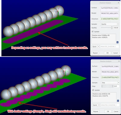
This inaccuracy stems from the calculation method (documented here). To calculate the Projected area of an entire part, a 1000 by 1000 grid is used for the calculation. In contrast, a numerically precise result can only be obtained for single Creo areas.
Proposed Solution:
- If the current grid calculation scheme is retained, allow users to select between a “standard grid size” and a “manual grid size” for projected area calculations, enabling a trade-off between accuracy and speed, as is common in advanced fluid simulations.
- Provide visual feedback on the chosen grid size directly on the projection plane, helping users assess result quality before calculation.
This visulisation helps to indicate whether the grid resolution is sufficient.
Currently, no visual feedback is generated at all. - The new tool should clearly indicate expected numerical deviations, preventing unexpected discrepancies for users.
(visualisation of workaround, see point 2.)
2. Are you using a workaround?
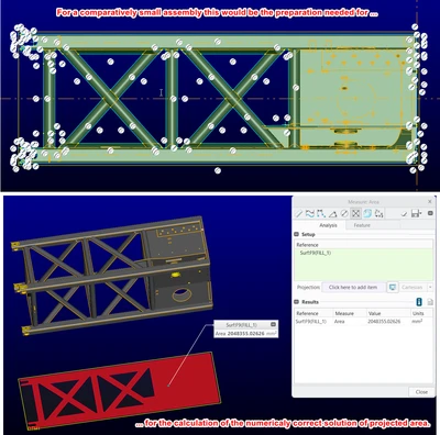
Theoretically, it is possible to define such a single contiguous area as mentioned above by project trimmed edges along an assembly contour. BUT this is a time-consuming and error-prone manual process that is not comparable with the previous GUI (Select assembly, select plane to project, projected area calculated). One realistic example is shown in the above screenshot. The automatically generated silhouette curve often requires extensive manual correction to define the correct projected surface.
3. What is the use case for your organization?
Accurate projected area values are essential for designing wind load areas and determining the resulting mechanical loads on components.
4. What impact does this problem currently have on your organization?
Designers and calculation engineers face uncertainty in component dimensioning due to inaccurate projected area calculations. This affects critical input variables for the safety-relevant design of load-bearing structures. Highlighting and addressing this deviation is crucial for improving long-term calculation reliability.