Feb 21, 2026 4:10 AM UTC
Acknowledged

Improve Full Round capabilities in Creo

Related products:Creo Parametric

1. Describe the Problem

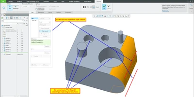
Currently the only way to create "Full Rounds" in the Found feature is if we select a pair of edge references.


There is a specific user case where we want to create a full round, but with the current Creo methology it is not possible, not even in the latest Creo version (12.4), and this use case happens quite frequently.


When we are designing "cooling" lines for parts in the molds industry, we frequently need "holes" whose bottom is a full round instead of planar or forming a "V" shape. The hole command only allows this two options, "Flat" and "Drilled" (tiipical 118º or 120º cone tip). Sometimes we use the "extrude" command to make "holes", and afterwards we need to make wither a full chamfer, or a full round at the flat bottom of the exreuded "hole".


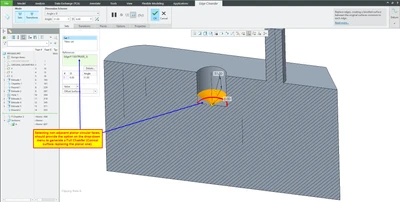
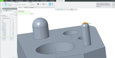
To increase productivity and avoid design erros or regeneration failures whe we change diameter of the holes, we need a way to apply full rounds to the flat bottom of the holes, but Creo currently does not allow it, since it does not allow selection of a single surface to fillet, it only allows selection of edges.


Creo allow creation of full rounds with two almost parallel edge selection that belong to a same surface. But we cannot use this method to apply a full round at the bottom of a flat hole feature or extruded hole, since the two halved of the circular face are nor valid selections to perform a full round.


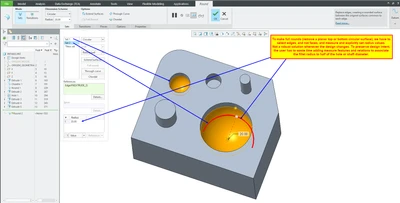
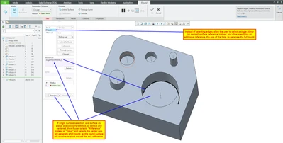
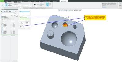
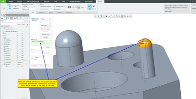
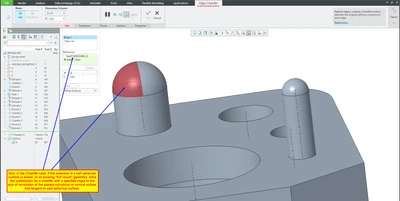
My suggestion is for Creo to detect this cases, when the user selects a single surface (the selector already allos selection of surfaces, but for other use cases (For surface to surface fillet creation, which needs a surface pair).


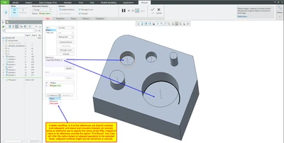
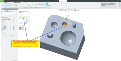
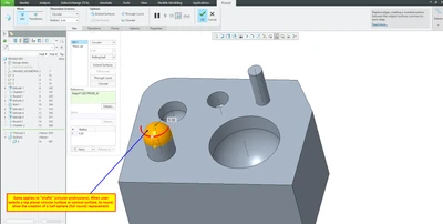
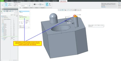
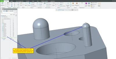
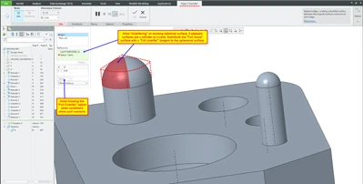
The idea is that if the user selects non adjacent surfaces (mainly planar circularly trimmed surfaces) (the flat portion of the bottom surface of a hole), and the adjacent surfaces of these selected surfaces are cylinders or cones, then it is valid selection to provide a full round or a full chamfer, meaning, to replace the planar face with a spherical half surface.


The possibilities of only having to select flat (or conical) faces instead of edges, has the added benefit that the user can be presented with the possibility to create a full round, instead of having to specify its value, since having to manually specify the radius value is prone to errors when the design changes, causeing feature failures, or creating a smaller fillet radius than intended and needed.


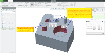
To have robust design, with designs prone to changes, the user would have to create first an analyse feature to measure the hole radius, and provide a relation to the fillet feature to use the same value. This is time consuming and decreases productivity. We only do it in UDFs, but they cannot be applied in most cases.
 

Face_Fillet_and_Chamfer_06.png

Face_Fillet_and_Chamfer_07.png

Face_Fillet_and_Chamfer_08.png

Face_Fillet_and_Chamfer_09.png

Face_Fillet_and_Chamfer_10.png

Face_Fillet_and_Chamfer_11.png

Face_Fillet_and_Chamfer_12.png

Face_Fillet_and_Chamfer_13.png

Face_Fillet_and_Chamfer_14.png

Face_Fillet_and_Chamfer_15.png

Face_Fillet_and_Chamfer_16.png

Face_Fillet_and_Chamfer_17.png

Face_Fillet_and_Chamfer_18.png

Face_Fillet_and_Chamfer_19.png

Face_Fillet_and_Chamfer_20.png


2. Are you using a workaround?
As a workaround, if we use UDFs, we can "waste" time by creating an analyse feature to measure the hole diameter, and provide a relation to change the fillet radius or chamfer value to half of the hole diameter. For ad-hoc feature creation, this is not possible or wastes too much time, so, what happens is that we measure the value, and assing the said value to the fillet. When the design changes, the hole becomes smaller, the fillet creation will fail, and the user hast to re-specify the correct value. If the hole is changed and gets bigger, there will be a silent error, meaning, Creo will not report it, but the fillet round or chamfer will be incorrect.

3. What is the use case for your organization?
Increase productivity for a use case that happens quite frequently. This is also a core capability that will increase productivity and better convey design intent for all the Creo users that need this core capability.

4. What impact does this problem currently have on your organization?
Difficult to estimate the time in hours due to lost productivity.

5 replies

Feb 23, 2026 1:27 PM UTC

How about having the hole creation wizard allow a rounded tool end as an option? This would allow the hole to change diameter and update the hole end, just like it does for an angle hole end.

Feb 23, 2026 7:54 PM UTC

Hello @BenLoosli ,


I'm glad you commented this.


This was supposed to be my 3rd suggestion, and I only remembered again to mention this after I left the office.

Indeed, it would be very beneficial to have this possibility to have the hole command or feature produce full round shaped bottom surfaces.

We need to have this when the parts have to be heat treated, since the V shape of holes tends to produce cracks more easily.


We tend to use a UDF with a sketched revolved feature, but is more time consuming to setup a plane to make a revolved feature than to extrude several holes at once (if they have the same depth), or use the new multi-hole feature with flat bottoms, and add the fillets later..


It would increase productivity to have the option to create the holes with the full round from the get-go.

Feb 23, 2026 8:39 PM UTC

I am using 12.4.3.0 and have no issues with creating a flat bottom hole and then applying a full round to the bottom by selecting the bottom edge. I did the same thing with an extruded cylinder. I set the radius of the round to the diameter variable/2 (d11/2) and when I change the hole or cylinder diameter, it updates including the round. While this is 2 steps, it does work. Am I missing something in your request?

Feb 23, 2026 10:44 PM UTC

To @BenLoosli 


Yes, you missed something in my request.

What I stated is not that we are not able to make a full round on the bottom flat surface of a hole or extruded circle.

We can, and we do it.


But as you stated, when selecting the edges, you have to know the value of the diameter of the existing cylinder to make the radius value half of the cylinder diameter.


If you change the diameter of the hole, the round will fail until you edit and re-specify again the radius with value to be equal of the diameter of the hole. For this to be automatic you have to add relations. If you don't add relations, the feature will either fail, if the cylinder diameter becomes smaller, or it will not fail, but will not provide a full round as intended, ans since it did not fail, the user might not even notice it.


My proposal aims to automate this process, to make it error proof, and avoid having to add relations to avoid slowing down the design process, and avoid erros when designs change.


With my proposal we can even add full rounds (as needed and intenteded) even if we select several bottom surfaces of holes or extruded circles in a single operation, and avoiding adding several analyze features and relations for each group of same diameter holes. It will depend only on the selected geometry (a flat circularly trimmed surface with ajacent cylindrical surfaces (in the simpler case), or a conical surface with eventually cylindrical or conical surrounding surfaces for a more generic solution). All automated based on selected geometry.

Community Manager
Feb 24, 2026 2:19 PM UTC
Status changed to: Acknowledged

Thank you @S_Edgenear for your idea. Based on the information you provided, we are acknowledging it as the Community management team. This is not a commitment from the Product team. Other users may comment and vote your idea up.