
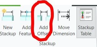
[Eztol] Add offset shown on dimension loop view in Eztol
1. Describe your environment: What is your industry? What is your role in your organization? Describe your stakeholders.
Chassis designer:use sheetmetal and solid in Creo Parametric & EZTol
2. What version of Creo Parametric are you currently running?
Creo 7.0.3 upgrade to Creo 7.0.8
3. Describe the problem you are trying to solve. Please include detailed documentation such as screenshots, images or video.
As below picture shown, this SMT component on PCBA doesn’t have any shaft or hole to align, so we need to use add offset to set the location. But added Offset isn’t shown on dimension loop view to make dimension loop view look oddly.
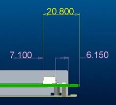
Because many Brand customers have their TA traditional method and TA format, and TA report is not only reviewed by ME RD. QA and more engineers need to check by the document as excel or html. Customer hope we can add some numbering icon or any mark to let reviewer can read easily.
4. What is the use case for your organization?
We use Eztol to build TA stackup and generate TA report. But TA report is not only recorded and reviewed by designer, QA and Customers also have to check TA report. So how the TA generate report viewed impacts user experience.
5. What business value would your suggestion represent for your organization?
We can push Customer to accept to use EZTol more easily. And If customer can accept EZTol, we can push digital transformation in our organization more easily.