Nov 3, 2025 4:21 PM UTC
Archived

during HOLE feature add ability to select more than one axis to get the same hole in another places

Related products:Creo Parametric

1. Describe the Problem

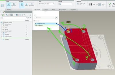
rsobecki_0-1762186793628.png

My idea here is that during Hole Festure user should be able to add more axis if the holes are the same shape


2. Are you using a workaround?
each hole need to be made separate

3. What is the use case for your organization?
low

4. What impact does this problem currently have on your organization?
low


Status changed to: Archived

Hello,

We are archiving your idea as part of a general review. This action is based on the age of your idea and the total number of votes received, as per this announcement.

You can always post a new idea with all the details required in the form.

Thank you for your participation.

This topic has been closed for replies.

8 replies

Nov 3, 2025 8:22 PM UTC

We use copy paste special, to guarantee the same dimension in identical holes.

The only problem is that if we pattern the first hole, we no longer are able to use it as a source to copy and paste it to other identical locations.


So, your ideia is interesting andd valid, the only problem I see is to make a correspondence between the other axis and eventual other faces.

If thei are located on the same face, in most cases a pattern would solve the problem, or a copy and paste special. But it would work faster with selecting a single planar face location and indeed be able to select multiple axis, in case a reference pattern cannot be leveraged.


Nov 3, 2025 8:39 PM UTC

This has been requested previously https://community.ptc.com/t5/Creo-Parametric-Ideas/Multiple-holes-per-each-hole-tool-use/idi-p/454391

It was archived due to "lack of votes" which in no way means it's not a good idea. Maybe there are others but I stopped searching.

I do prefer to use copy/paste special but the concept of being able to place multiple holes quickly (non-pattern type holes) is certainly tempting! Although I'm afraid it would be used for evil, like putting all the holes separately when they should be a pattern, but that's a user training issue instead of a valuable feature problem. 

Nov 3, 2025 8:43 PM UTC

To @mneumueller 


I think in this use case, the hole command could be futher improved in two ways.

After selecting a planar face for hole start location, if the user selects a cylindrical face instead of an axis to locate the concentric holes, the user could have two additional benefitts that would speed up operation and leverage design intent:


a) Allowing to select cylindrical faces instead of axis to position concentrical holes, and with an additional check-box the to confirm, Creo could perform an internal pattern recognition to locate identical cylindrical surfaces positioned on the same planar face, similar to pattern hole recognition in Flexible modelling. This would allow Creo to perform an internal pattern of the hole command similar to the "Sketched Holes" introduced in Creo 8, and would deliver the improvement that @rsobecki suggested/requested.


b) By allowing to select the cylindrical surfaces of the "through" hole, Creo could be improved to automatically select the Screw Size of the hole ,if it's a standard hole, that the user selected. At least for ISO holes, with standard thread (no fine threads), only one screw size would fit in the requested through hole. So, Creo could automatically select the hole size M6, M8, M10, etc, based on the Thread Standard selected. This would ensure that hole screw sizes would be always valid if the user changed the Through hole in the other part or other body, making it possible to make associative and parametric hole dimensions on a first hole dimension.


*PS: As an asside note, and for other use cases, the standard hole command could also be improved to allow to make standard holes in multiple-bodies in a single operation. Currently the hole command can work on several bodies, or through all bodies, but if the user wants a standard hole, he has to perform at least the hole features, one to specify the through hole (with eventual counterbore or countersink), and another hole feature for the tapped portion of the concentric holes. And there is no way the user can make any association of Screw Size between the two features. He cannot even make a relation even if would want to take additional time to guarantee design intent. The only way is to use UDFs or use simple holes and apply a "Cosmetic Thread" to be able to make relations. Which is also not convenient, and also a little bit time consuming. So, a single hole feature for multibody use case, that would let the user pick which of the bodies would be the "final" body to receive the "tapped" portion of the hole would really allow to work much faster for the cases where the user uses multi-bodies to define skeletons from which to derive parts for assemblies.

Nov 3, 2025 9:05 PM UTC

Another advantage of being able to select cylindrical surfaces (Creo could check that there are two halfs of a cylinder if the user wants to appply standard holes, and that those cylindrical surfaces have the same diameter (for the different locations), and even if the user selects a Screw Size that the selected surfaces (from a through hole) have diameter compatible with the selected screw size), is that it would quickly allow to create concentric holes even for imported geometry that has no axis on the cylindrical surfaces center.


As a workaround the user could create a flexible modelling feature to recognize identical or similar holes, create an axis on one of them, and then reference pattern the axis to be able to select said axis for a concentric hole, and after pattern the said hole. It works as a workaround, but for such a common task, it reduces user producitivy.


Another workaround is also to sketch on a plane points to define hole centers based on user selecting cylindrical surfaces and placing a point at the center of the cylindrical surface projection on the plane. This also work and allow the user to either use the sketched points to place a hole on the first point, and then create a point pattern of the hole, based on this sketch. Or we could also directly use a "sketched" hole feature to create the multiple holes. The problem with this workaround, in this case, not for imported geometry, but for parametric geometry, is that if the number of holes changes, one is deleted, or other holes added, the user will have to edit this skech to add another point, or remove one of the existing points after failure. So, this solution is not robust for designs subject to frequent changes.

Nov 3, 2025 9:07 PM UTC

Another way to solve this issue, is to allow the "Axis" feature to be modified to allow the selection of multiple cylindrical faces.

If the point feature can have multiple-points, why not also allow the axis feature to have multiple references? A rule could also be added to also only allow selection of paralell axis at multiple-locations.


So, if the user wants to create a concentric hole and selects an axis that belongs to a multiple-axis feature, the other locations could be automatically be included and the hole be created as an internal patten.

Nov 4, 2025 1:04 AM UTC

One more thing related to this topic.


Even if Creo changes to be able to multi-select multi-axis or multi-cylindrical surfaces to make several holes at once, I think the Axis feature could also be modified to allow selection of more than one axis. similar to Datum Point, which allows the direct creation of a single datum point, or an array or list of several datum points. And this datum axis feature could allow the creation of several sets, similar to round feature with several round values, which would allow the user to select a cylindrical face, and with a check-box would select identical or similar axis of the same diameter on holes located on the same base surface. The user could select another cylindrical surface of another hole, and Creo could select also automatically similar or identical holes, and on each set, would be saved a read-only parameter identifiying the diameter of the hole. This metadata could later be leveraged on the hole command to create several holes at once, and would know for each set the diameter of the screw hole that the user would need.


This possibility to create several axis at once on a single feature is important and a time saver not only to put axis on imported parts, but also on copied gemetry, or merged parts (no inheritance) since in this case the user could not leverage any information related to patterned holes on the base parts. When users have to make 2D drawings and manually add axis on several holes, it's a slow process of user interaction.


When creating an axis feature, the last axis becomes pre-selected. So, if the user needs to create more, first he needs to right click on the background graphics window to de-select the last axis, otherwise he will create another overlapped concentric axis over the last one. So, this process is tedious.


Nov 4, 2025 1:10 AM UTC

On a related note to my last comment, of allowing faster creation of mutiple axis, is also the creation of multiple center ponts. Currently the Datum point feature allows creation of points on the center of arcs or circles, They can be datum curves or edges. But if the user needs to create several center points centered on several arcs, he cannot pre-muti-select the arcs or circles to create all the centered points at once. He must select the arc or circle one by one, and go to the reference option of each selected entity and change the option from "On" to "Center". It would be a time saver if the user could pre-select the condition "On" or "Center" before selecting multiple-reference arcs or circles. Maybe a right click menu over the point list to allow bulk change of the condition of the selected points (if they all reference arcs or circles).

Community Manager
Nov 4, 2025 12:11 PM UTC
Status changed to: Acknowledged

Thank you @rsobecki for your idea. Based on the information you and @S_Edgenear @StephenW provided, we are acknowledging it as the Community management team. This is not a commitment from the Product team. Other users may comment and vote your idea up.