
Feb 3, 2014 5:15 AM UTC
Archived

Depth of Extrude

Related products:Creo Parametric

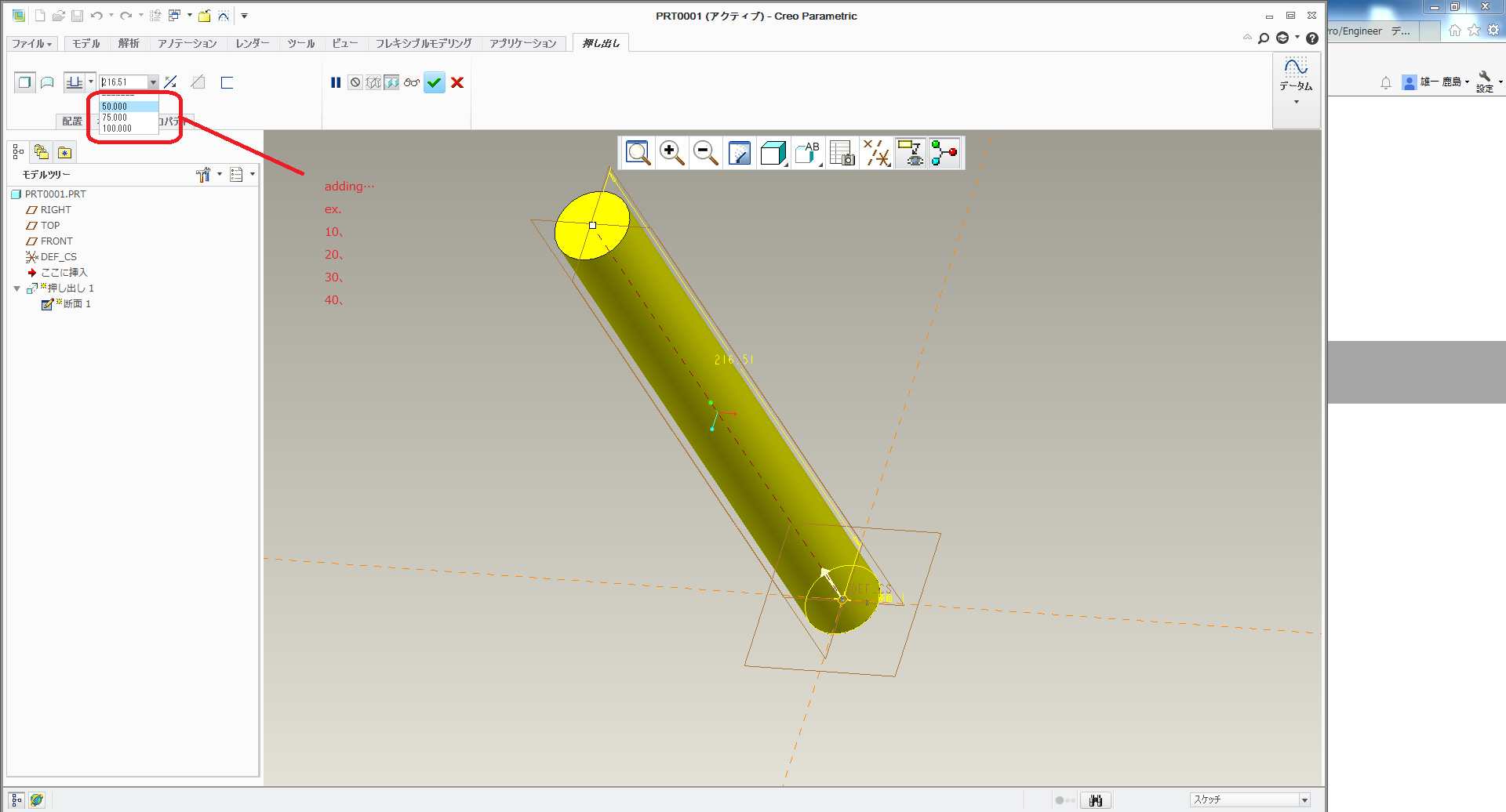
Depth of Extrude is 216.51 at first

I want to set default depth.

if you make a small part,

you can't look for handle of Extrude's preview.

So it's hard that you control.

I propose 2 ideas.

1 . Setting default Depth of Extrude by config.pro.

2 . adding small size depth in dashboard menu. ...like 2.png
2.png

8 replies

1-Visitor
Feb 3, 2014 6:37 AM UTC

You should vote up your own idea!

Because you forgot that, please vote up that one too:

When creating a new product idea, it automatically adds a positive vote for the creator.

Feb 3, 2014 6:37 AM UTC

I'm all for a default bounding box setting in config.pro.  Let it change after you create the first geometry feature, but it would be very useful if all your parts started out being less than 6 inches.

Feb 3, 2014 7:09 AM UTC

jt.jpgHow about UDF for default depth or trail files for dashboard?

As you know UDF is able to have fixed depth/length.

And, you can use a trail file to input the values up to 5.

Please try my trail file. I'll send the file to you soon.

Feb 3, 2014 8:20 AM UTC

Thank you very much.
I could use your trail file and checked 10-50 in dashboard!

UDF is able to have fixed depth if you do in the order of 1-4.

1. Select "Sketch"
2. Select "Plane"
3. Sketch curves
4. Select "Extrude"

But UDF isn't able to fixed depth if you do in the orider of 1-3.

1. Select "Extrude"
2. Select "plane"
3. Sketch curves

Feb 3, 2014 2:05 PM UTC

This was brought up at the TC meetings a couple of weeks ago and it looks like they wanted to do something about it. Not sure if this could make it into Creo 3 in time or maybe be back ported.

Aug 1, 2017 6:27 PM UTC

Posted on another similar post and was directed here, you have my vote.


Below is a tip:


This tip is a work around to this issue that you may want to adopt until PTC develops a OOTB solution:


  1. Create a new part or assembly using the standard template.
  2. For the first feature create a sketch circle, assign a dimension value that would represent the size of the part you are creating. In below example I created a 10 inch circle on the Front Datum Plane.

2017-08-01_12-25-43.png


3. You can know create your sketch as normal (make sure you do not reference the sketch circle, this will be deleted later). In example below I sketched an “L” shaped extrusion.

2017-08-01_12-30-59.png

Note that the dimensions of the “L” shape are more in line with the size of the circle created in step 2.

 4. Completing the extrude also does not default to a 216.51 extrude depth and allows you to select the drag box to resize without panning and zooming operations.

2017-08-01_12-34-13.png

5. The last step to remember to do is to delete the circle sketch. As you can see below the datum’s are still scaled to the circle sketch.

2017-08-01_12-37-51.png

NOTE that deleting the circle sketch changes the size of the datum’s to match the part.

2017-08-01_12-40-40.png

Jun 14, 2018 7:23 PM UTC
Status changed to: Acknowledged
olivierlp
Community Manager
Jan 4, 2022 2:06 PM UTC
Status changed to: Archived

Hello,

We are archiving your idea as part of a general review. This action is based on the age of your idea and the total number of votes received, as per this announcement.

You can always post a new idea with all the details required in the form.

Thank you for your participation.

Olivier