
Assign Line Type Scale to Line Fonts when Exporting DXF/DWG Format Drawings
Please include detailed documentation such as screenshots, images or video.
1. What product and version are you running?
Creo Parametric 7.0.9.0
2. What is the problem?
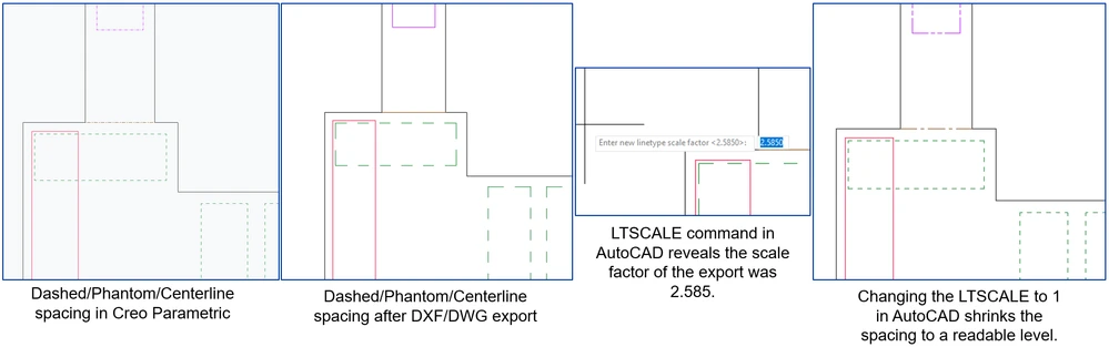
I have a drawing with multiple dashed line fonts. In Creo Parametric, the spacing of these line fonts changes dynamically as I zoom in and out so that they are always readable. When I publish the file to a DXF or DWG format, Creo appears to be assigning a linetype scale factor that I cannot control. When I import the resultant DWG file to AutoCAD, I can use the LTSCALE command to enter a new scale factor. I see when I do this that Creo has assigned the factor 2.585 for this particular drawing. Other drawings have their own scale factors applied, I assume based on the size of the drawing sheet (larger sheets get larger scale factors, resulting in wider spacing).
See community discussion that led to this idea post:
3. Are you using a workaround? If yes, please describe it.
One potential workaround is to open the exported DWG in AutoCAD and manually change the LTSCALE value as a post-processing operation.
4. What is the use case for your organization? Describe how your idea would work in context or how it would apply to a practical situation.
As it stands, drawings with dashed lines often appear solid in the DXF/DWG export, which confuses anyone reading the drawing. Allowing Creo to control the scale prior to export would go a long way to reducing that kind of error. For example, a dashed line may represent a feature on the far side of a part in a drawing. When exported to a DXF/DWG, that dashed line appears solid if the spacing is too wide. Anyone reading that drawing will think the line should be solid, and may construct or inspect that part incorrectly.
5. What impact does this problem currently have on your organization? (Number of users affected, hours of lost productivity, etc.)
Drawing misinterpretation leads to scrapped parts, rework, non-comformances, and other costly situations.