
May 7, 2013 1:46 PM UTC
Archived

Allow correct display of Datum flags in 3D Annotations

Related products:Creo Parametric

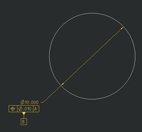
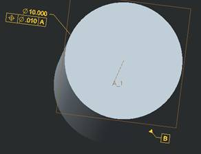
In 3D Annotations, allow a datum flag to correctly "hang" off of the GD&T box like in a 2D drawing.

Here is what it correctly looks like in 2D:
2D-datum_image.jpg

Here is what it incorrectly looks like in 3D:
3D-datum_image.jpg

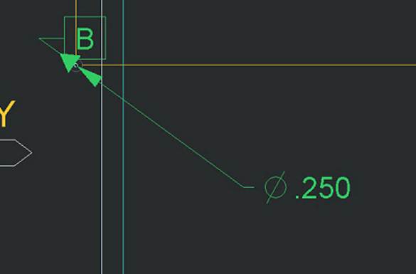
Regarding the location of the datum flag in general, there does not appear to be a way to where it ends up in a 3D Annotation.  See below where the datum flag would normally be attached to the leader line:
3D-datum_image-on-hole.jpg

4 replies

May 7, 2013 4:19 PM UTC

I hear you on the ASME Y14.41 implementations of datum tags.  It is a real problem in making a good looking view.  Even in ASME Y14.5 (2D), managing datum tags is horrible.

However, if the GTOL on the diameter 10 is real, you can hang the datum tag from the frame.

One of the huge problems I have with cylinder datum tags is that they don't want to move.  You should be able to move the "point on surface" to anywhere along that cylinder with ease in both 3D and 2D.

datum_on_gtol.JPG

Remember to vote for your own idea

May 30, 2013 10:50 AM UTC

I thought this was a glitch and I was doing something wrong, after mucking around with it for 30 mins I came across this and realized it wasn't even possible to get the 3D display right but the drawing would look correct!

Feb 5, 2015 6:56 PM UTC

In a related note, I just found out what the different button settings mean:

Change Datum Tag Symbology to reduce confusion

http://communities.ptc.com/ideas/5311

Mar 16, 2019 2:26 AM UTC
Status changed to: Archived