
Add polar/angular ordinate dimensions with parallel to witness line text orientation
1. Describe your environment: What is your industry? What is your role in your organization? Describe your stakeholders.
I am CAD administrator for a company that manufactures powered two-wheelers (those that you can sit on).
Stakeholders would be design engineers and suppliers/manufacturing engineers.
2. What version of Creo Parametric are you currently running?
4.0 (8.0, 9.0)
3. Describe the problem you are trying to solve. Please include detailed documentation such as screenshots, images or video.
I am trying to achieve a dimensioning scheme like this:
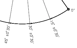
ISO 129-1 (2004) section 8.3:
Dimensional values may be placed either
- near the terminator, in line with the corresponding extension line...
4. What is the use case for your organization?
ISO 129-1 compliance.
More robust dimensions.
5. What business value would your suggestion represent for your organization?
Time saved by less manual tweaking of the dimensions.
Standards compliance.