
Jun 14, 2023 12:17 PM UTC
Acknowledged

Ability to adjust the angle of an extrusion

Related products:Creo Parametric

We have Creo 7 in use and have the Idea to improve the extrude functionality to be able to modify the angle of the extrusion so that it is not parallel to the sketch and can be modified by just changing an angle.

Right now, it is needed to create a datum plane under a certain angle to create the angular extrusion or maybe use flexible modeling to modify the existing extrusion.


If it would be implemented inside the extrude feature itself the extrusion could be modified by just defining an angle. 
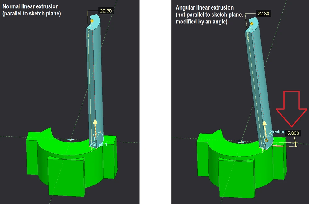
 

16407_Angle_extrude.png

8 replies

Jun 14, 2023 12:33 PM UTC
Status changed to: Clarification Needed

Thank you for publishing your idea. However, we need more information as specified in the form you saw in the submission process. (questions below). You may simply add a comment to your idea. The more details and context you give to document your idea, the better. Think about ways to educate and convince other Community members to support your idea and present your case to the product management team for consideration.

Please let us know within the next two weeks.

1. What version of the software are you running?
2. What is the problem?
3. Are you using a workaround? If yes, please describe it.
4. What is the use case for your organization? Describe how your idea would work in context or how it would apply to a practical situation.
5. What impact does this problem currently have on your organization? (Number of users affected, hours of lost productivity, etc.)


Here are a few examples of well documented ideas:

Make Shrinkwrap quality more scalable to data size... - PTC Community

Improve/fix the sheetmetal mirror feature - PTC Community

[Eztol] Rename action not synchronous in Eztol - PTC Community


Additionally, I invite you to check out this topic where PTC executives explain product managers' approach to customer ideas and input for product roadmaps.

Jun 15, 2023 11:44 AM UTC

1. What version of the software are you running?

       We are using Creo Parametric 7.0.5.0 as productive version, but it is also not part of Creo Parameric 9.0.3.0 

2. What is the problem? 
       It is just not possible to make an extrusion that is not perpendicular to the sketch inside the extrude feature.


3. Are you using a workaround? If yes, please describe it.

      Yes, sure there is another way to create that kind of geometry but for that you need to create additional 3 features to make new datum plane
      with a different angle.


4. What is the use case for your organization? Describe how your idea would work in context or how it would apply to a practical situation.
      - Less number of features inside the model tree
      - More overview (less datum planes )
      - Easier and faster workflow for the design

5. What impact does this problem currently have on your organization? (Number of users affected, hours of lost productivity, etc.)
      The impact to the organization is difficult to measure. An improvement of this workflow will speed up the design because all functionality to
      have that geometry at the end is done by just a few clicks more (or pulling on a drag handle) instead of creating several additional features. 

Jun 15, 2023 1:00 PM UTC
Status changed to: Acknowledged

Hi @OliverHeins!

Based on the information you provided, we are acknowledging it as the Community management team. This is not a commitment from the Product team. Other users may comment and vote your idea up.

Jun 15, 2023 11:25 PM UTC

Sounds like a good addition to the tool

Jun 16, 2023 10:54 AM UTC

Angles are rarely independent dimensions. They need a pivot. The same sketch could generate varying geometry based on the pivot.  Thats why you cant just say I want a datum plane at 30º, you have to have a plane (in your case, the angle reference would be the sketch plane) AND a pivot (usually and axis)

Jun 16, 2023 3:13 PM UTC

Of course there must be references for the angle, as you say the sketch plane would automatically be the reference as the basis for the angle measure. From my point of view, it only needs an additional reference for the direction in which it should be tilted.


In this case, that would be the selected model edge, axis, datum plane ... as the direction reference. Based on the selected reference, you could also use a drag handle to somehow change the direction in which the profile is to be extruded linearly.


16407_Angle_control.png

Jun 16, 2023 3:37 PM UTC

Sounds like something that could easily be accomplished with a sketch and sweep.  Use Constant Normal Direction and select a reference for the normal direction.  In the image below, the section is parallel to the top plane and follows a line tilted 20 degrees from perpendicular.


kdirth_0-1686929498989.png


Jun 20, 2023 7:11 AM UTC

@kdirth 


There is no question that this can of course also be generated with the sweep feature. In that case it is actually the simplest form of it and also a special case for this function with a linear trajectory. The really powerful thing about the sweep function is if  the trajectory is not straight, but can take a different course. If I want to use this function, however, I need at least one sketch with a linear curve and maybe also a plane on which I sketch the trajectory, so again an extra construction element in the model tree and an extra step in the konstruction.


As already mentioned, this idea is not about the fact that there is no other way to create the geometry, but about improving the workflow and thus improving the user experience. Having this option within the extrude function would mean to have just an extra click for the angel reference and adding the angle value (or pull on a drag handle).