
Re: shear&moment diagram
Hi Joey,
Let's start with the first problem (ex1.prt.1). Here's what I'm seeing in your post:
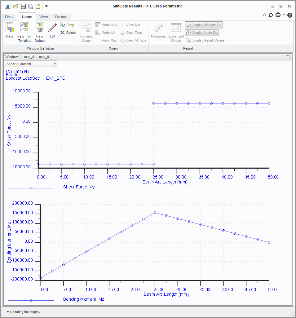
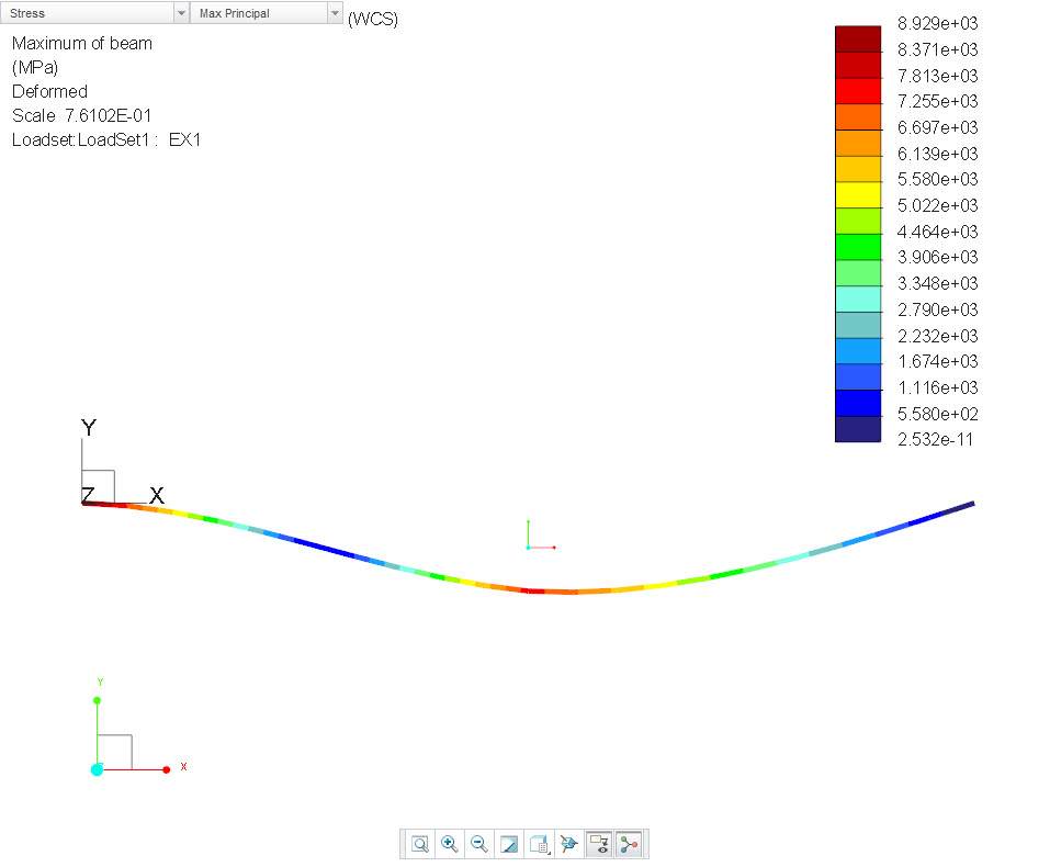
1. The shear-moment diagrams don't match your blue beam sketch because you ran an analysis with both ends of the beam fixed in xyz. The shear diagram shows -10 then +10, and that's what you get when you fix both ends. However, your example shows a fixed end and then a roller on the right side. To simulate a roller constraint, free the X translation and free the Z rotation.
2. The greatest moment is in the center of beam, and this would not be zero.
3. The shear-moment graphs show a beam length of 50mm, but the sketch show 5cm.
4. Modeling hint: You don't have to sketch the curves to make the beams. I made the beams point-to-point. Make all your points first, then connect the points with beams in Creo Simulate. Look at the file I uploaded as an example.
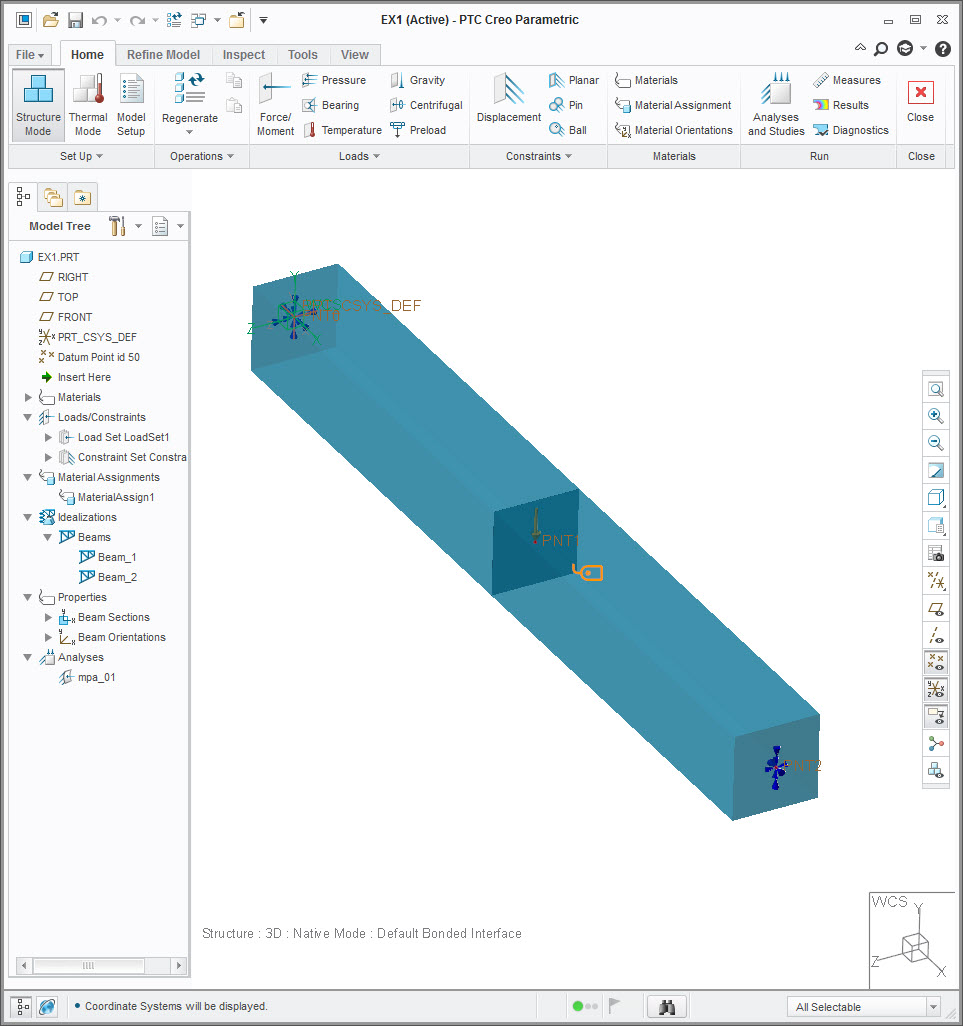
File uploaded.