May 22, 2014 10:59 AM UTC
Question

Re: Fastener "separation stress" measure

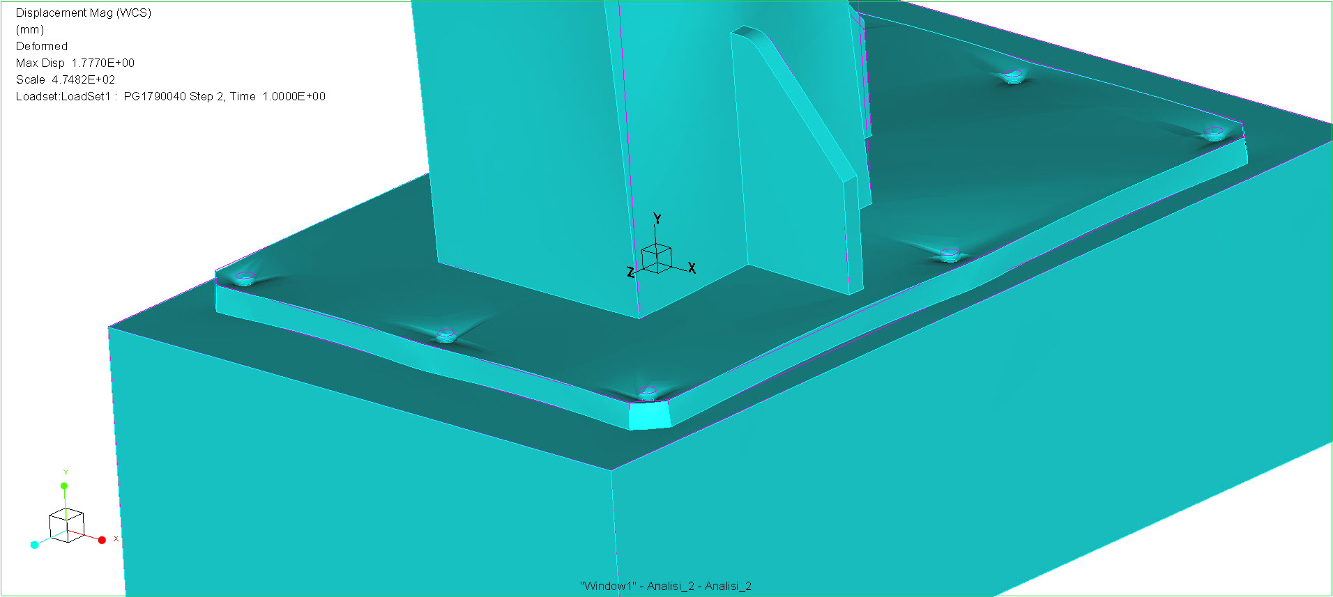
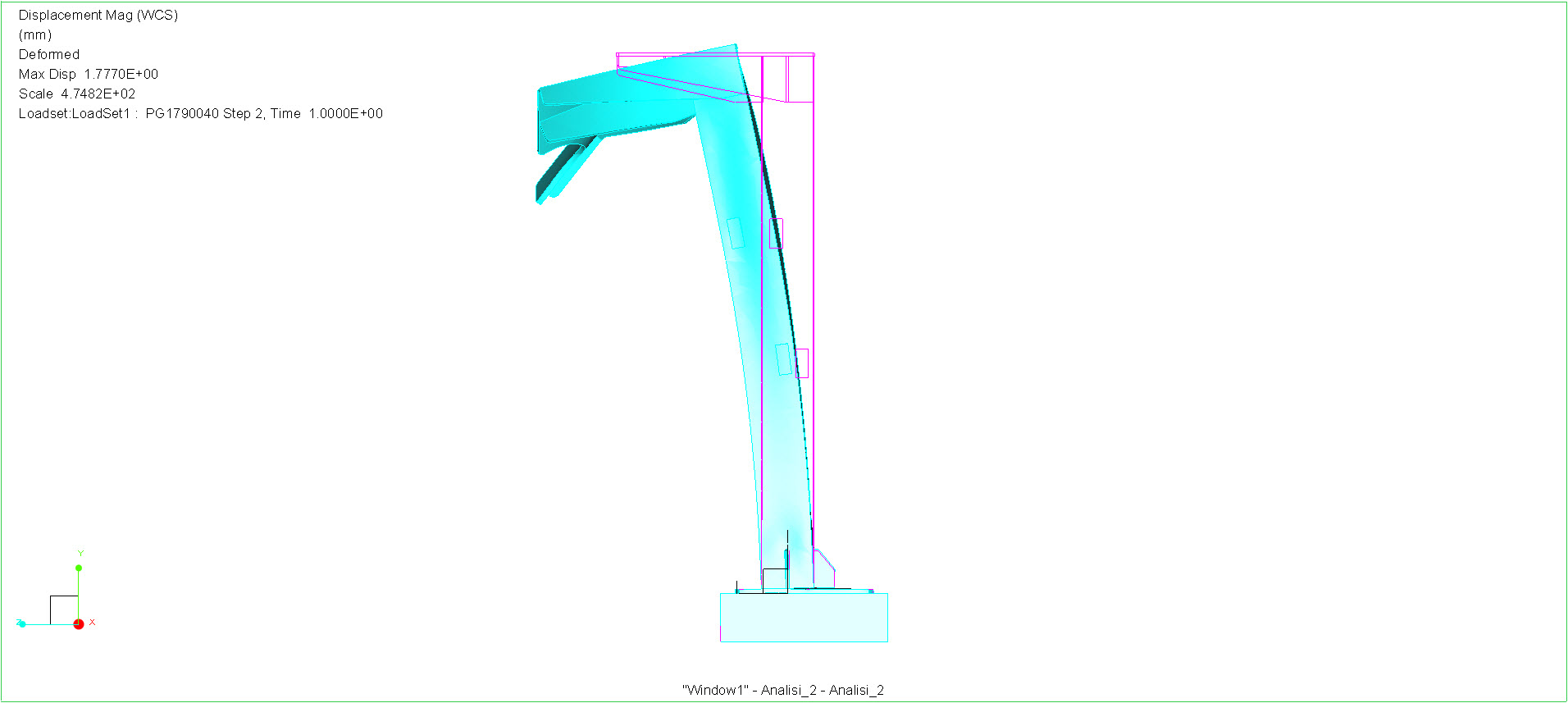
I ran the model, and I think the reason all of the fasteners are positive for axial force is that the plate is trying to lift off the block at every fastener location. You have a 200kg mass at the top which is offset from the center of the support beam, creating a moment to lift the base plate off the block due to a gravity load. I deformed the assembly at 30% to illustrate this, as shown in the three figures below:
seperation_stress_01.jpg

Figure 1: Deformed With Overlay

seperation_stress_02.jpg

Figure 2: Plate Lifting at Each Fastener
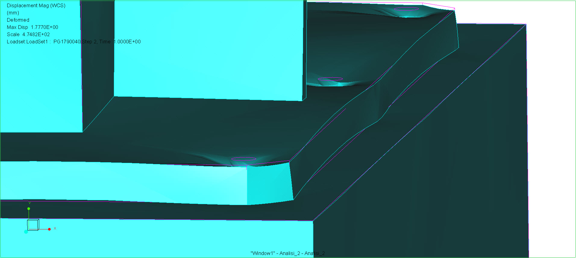
seperation_stress_03.jpg

Figure 3: Plate Lifting, Deformed and Overlay

    3 replies

    May 23, 2014 7:43 AM UTC

    Nuova+immagine.jpg

    I've done others analysis with only 4 screws (because my colleague civil engineer said me that the floor's cement would have resist better with less screws but more spaced) but the reasoning it's the same.


    In Analisi_4 end 5 I've removed the floor (pavimento.prt) and I've fix the hole of the screws putting on each of them a measure of force along Y direction.

    In Analisi_4 I've removed gravity and substituted the mass of load with a force: in this manner I'll go to measure only the load given by the load.

    In Analisi_5 I've removed the external load and I've resetted the gravity, so you'll go to measure only the load given by mass of the structure.

    Utilizing the "overlap of the effects" you'll see that only in the positions 2 and 3 the reactions are negative (so the direction is downward), and this is reasonable because the structure tries to rotate around the red edge in "im_2" picture.

    Im_2.jpg

    What I don't understand is the right manner to utilize the fastener in mechanica, how to apply the preloads and how to read the real axial stress.

    According the Analisi_4/5 the screws near the "red edge" are not loaded, but in Analisi_2, where I used preloaded screws, on each screw the measure of axial tensile stress is higher than the stress given by the only preload: this means that utilizing preloaded fasteners you'll find that each screw takes a portion of the external load, that is not true.

    Jul 11, 2014 4:59 PM UTC

    Hi Giulio,

    Your answers are correct and I agree it does seem illogical. I will explain ...

    First check the measures are adding up :

    TOTAL fastener tensions = EXTERNAL loads + INTERFACE loads

    (Total fastener tensions is the tension of all fasteners added together)

    This is to ensure that there is no unintentional load path where elements have joined together across the interface where they should not have. A few elements can carry tonnes of force and mess up the answer.

    I had a quick look at your model and the numbers do add up (it is always worth putting reaction measures on all constraints, this helps with free body diagrams and debugging)

    Now the explanation proper.

    Your structure does not pivot about the red edge you highlighted above. The fulcrum is inboard of that edge at the corner of the upright (PG1790040S002) and the base (PG1790040S001).

    As the main upright (PG1790040S002) is bent over due to the mass and self weight, the front edge of the upright (PG1790040S002) pushes the base (PG1790040S001) against the pavement at that point and the side gussets (PG1790040S005) which are behind this edge but in front of the middle fasteners lift the base plate.

    The small angle the base plate rotates x the distance from the the fulcrum to the gusset is greater than the bending of the plate in front of the fulcrum thus the base plate is thick enough (stiff enough) to pull the front fasteners up.

    The explanation for the rear fasteners' tension increase is more obvious, they are preventing the rotation about the fulcrum and are being lifted by the base plate which is pulled by the rear gusset.

    Eur+Ing+Charles+Simpson+CEng.jpg

    A refined mesh at the contact interface gives a better view of the contact pressure distribution between the base and the pavement and hopefully helps explain the true fulcrum location (which is slightly eccentric due to the loading)

    Oxford+Analysis+Consultants+Limited.jpg

    Although the front fasteners see more tension and the contact force at the front fasteners is reduced, as a first pass the change in contact load at the front fasteners is small and the fluctuating load well within fatigue limits of a cut fastener.

    ... your M12 8.8 fasteners could not be tightened to 80% yield in tension unless there was zero thread friction. There is a shear stress component that has to be added to the tensile component. sigVM=sqrt(tensile^2+3x(Tau^2)) and so a more realistically achievable tension is 35000 N for 80% material not 43000 N. (assuming a perfect torque wrench and no scatter).

    Regards

    Charles

    Jul 17, 2014 2:24 PM UTC

    Hi Charles,

    on Shigley "Mechanical and Engineering design", on cap. 8.9 in my version, it gives reccomended values of preload for bolts.

    Fi = 0.8 * At * Sp (preload)
    where Sp = 0.85 * Sy

    Cattura.JPG

    I forgot a " *0.85" taken 640 MPa as Sp when instead it is Sy.