
Jun 22, 2016 12:25 PM UTC
Question

Re: Element edge discontinuities

Garrett,

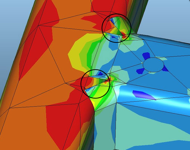
Difficult to determine based upon the fringe plot.  It appears that you have gaps between shell elements, and I circled these two region in the below image.  Can you upload an image of this same area before meshing?
discont.jpg

    1 reply

    Jun 22, 2016 12:48 PM UTC

    Hi Steven,

    You are correct that there is gaps between to the two shells.  Here is the native Creo part with welds.  In Simulate I use the "Weld Feature" selection to pick the welds.  The triangular shaped gaps in the shell elements occur because those are part of a different weld feature (shown by the black triangles in the second image) and Simulate wasn't able to create shell elements using this particular weld feature.  However, I've had this discontinuity with things as simple as two orthogonal plates with a fillet weld between them. 

      Weld Area.JPG  Weld Feature.JPG