Jan 13, 2016 2:21 PM UTC
Question

Re: Does anyone know the trick to Match Draft

Paul,

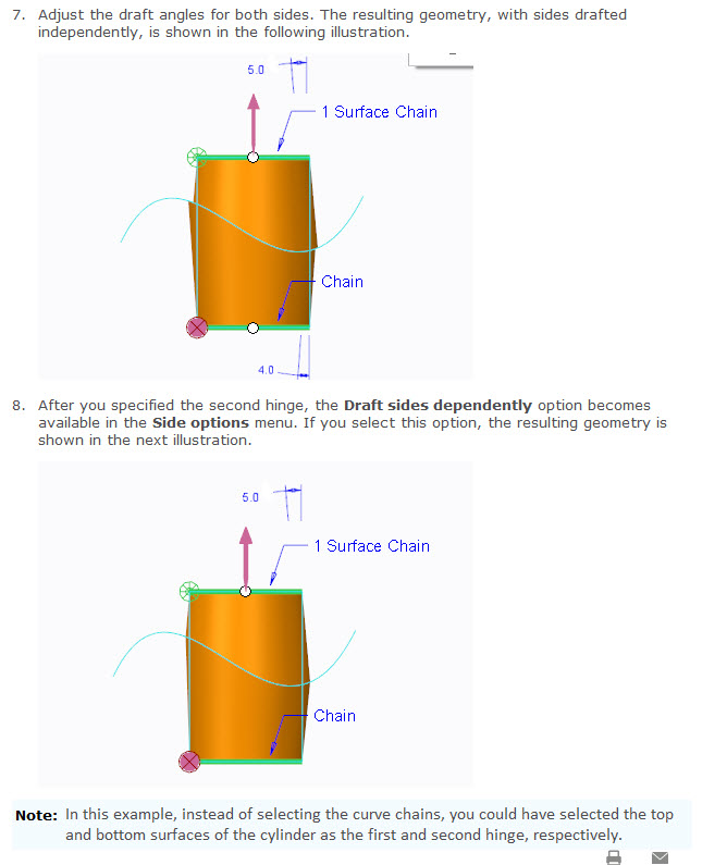
See if this helps.  This example has a curved plane whereas your's has a flat plane.
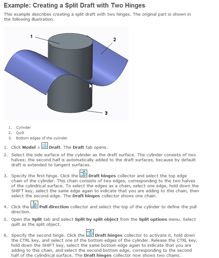
split_draft_1.jpg

split_draft_2.jpg

    16 replies

    Jan 13, 2016 4:11 PM UTC

    Steven,

    I really hoped this would work.  I tried variations of the same idea, but invariably I am getting the same result as shown.

    MatchDraftTested.JPG

    By selecting the 2nd hinge after applying the split object it does act different, but this just doesn't want to calculate.

    If anything my situation appears simpler than the document that you attached.

    This is very perplexing.

    3-Newcomer
    Jan 13, 2016 4:35 PM UTC

    What are you using for your draft direction?  It appears to be trying to use the green surface or something parallel to it.  You should be using a surface normal to your extrude.

    The draft direction determines what zero draft would be.  Zero draft will make the drafted surfaces normal to your selected draft direction plane.

    Jan 13, 2016 4:58 PM UTC

    If I use the top and bottom faces instead of chaining the edges I can actually get the draft type that the document you attached.  Albeit this didn't work at a full 5 degrees.  The worst problem however my coworker pointed out to me.  The match only applies to the 1st hinge side and not the other.  I would need the sides to grow on both sides of the split face.

    MatchDraft1Side.JPG

    It's cool that this itself works, but as you can see the right side needs to grow outwards.

    Doug:  I'm still not sure whether I'll be able to get anything to work properly, but I think I'm seeing that I might have an issue with my draft direction.  I thought that the long sides would drive at 5 degrees and the short sides would match draft.  I'll review this and see if I can get a better result.  What is confusing is that the split plane will be the draft direction as it will be flat in the dies.

    3-Newcomer
    Jan 13, 2016 6:56 PM UTC

    Creo did what you told it to do:

    • Draft this at 3.3 degrees relative to the split plane (the top side anyway)
    • Make the two sides dependent on each other (make them meet in the middle)
    • Maintain the surface position at the top and bottom (your draft hinges)

    What's interesting here is only the top section is really drafted at 3.3 degrees, the bottom is drafted to match it at the split quilt and to maintain the bottom edge.  It's essentially doing what I suggested above, but in one feature.

    If your part will lie in the mold so that the split plane is horizontal, what you want to do is not moldable.  Turning your view above so the split line is horizontal creates an undercut if you have to maintain the top and bottom profiles.

    If I understand what you actually want (and I'm sort of guessing here), I think you want your part in the mold as shown above and the draft direction then would be the horizontal plane in the middle (DTM_ABA?).  Your mold will open perpendicular to this plane but your P/L will be angled.  I think that should produce what you want.

    Jan 13, 2016 7:42 PM UTC

    Doug:  Actually the split is where the draft plane is located.  That is the reason for it's split location.  The model was created with ABA being the construction plane not the draft plane.  The oblong feature is tilted away from the draft plane.  The majority of the part would be in our draft plane that is why we are making an otherwise simple feature more complicated.