Nov 24, 2015 9:34 PM UTC
Question

Creo Drawing Cross-Hair

Community,

How do I make cross-hairs over circles in Creo Drawings?  I'm currently using Creo Paramteric 3.0 M060.
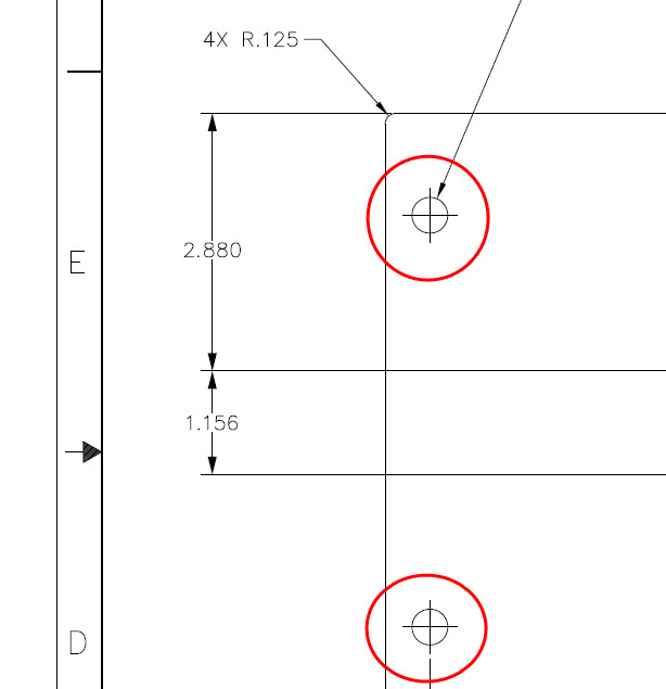
cross-hair.jpg

    6 replies

    Nov 24, 2015 11:36 PM UTC

    Show the axis.  Might have to go back and add one if needed (i.e. it's a cut).

    Nov 25, 2015 8:48 AM UTC

    Steven,

    just little note ... YES, in default CR3 color scheme, axis crosshair is displayed in brown color on the screen. User can configure pentable to print crosshair in black color - see datum_color keyword.

    Example of pentable:

    ! user color
    pen  1   thickness 0.015 cm

    ! dimension lines
    pen  2   thickness 0.015 cm; color 0.0 0.0 0.0;  letter_color

    ! hidden edges
    pen  3   pattern 0.5, 0.2 cm; thickness 0.015 cm; color 0.0 0.0 0.0;  half_tone_color

    ! text entities
    pen  4   thickness 0.035 cm; color 0.0 0.0 0.0;  edge_highlite_color

    ! tangent edges displayed as Dimmed
    pen  5   thickness 0.015 cm; color 0.0 0.0 0.0;  dimmed_color

    ! datum features (for example axis crosshair)
    pen  6   thickness 0.015 cm; color 0.0 0.0 0.0; datum_color

    ! visible edges - solid & sheetmetal
    pen  7   thickness 0.05 cm;  color 0.0 0.0 0.0;  drawing_color, attention_color

    MH

    Nov 25, 2015 2:30 PM UTC

    Only way I know to get that would be to use a sketch feature in the model and then set the properties of the sketch so the lines are black.x-hair-model.jpgx-hair-dwg.jpg

    Nov 25, 2015 6:10 PM UTC

    So how did you do it?

    Nov 25, 2015 6:20 PM UTC

    If that is a shown axis, that would be based on a how "long" your axis is.

    In image below, both are axis, one is just "stretched" longer than the other.

    axis-length.jpg

    Dec 1, 2015 1:49 PM UTC

    There are some axis controls in the .DTL file (File > Prepare > Drawing Properties > Detail Options). I just played around with it a little but I couldn't get it to match your request.

    I don't think you're going to find that for one reason: the centerline of a hole (also called an axis) is represented by a line using the centerline font (long dash, short dash, long dash, short dash, etc.) This is a drafting standard that predates computer use for creating engineering drawings. A small enough hole with have the 'solid cross-hair' axis but anything with enough size to accommodate it will use the centerline font.
