Jun 25, 2023 7:43 PM UTC
Solved

Offset Coordinate System Datum Point in Creo Drawing Table

I have created a pipe in part modeling using Offset Coordinate System Datum Point and want to bring points to the drawing table. Are there any solutions to read points coordinate (x,y,z) in a way when they are modified in the part, the drawing update table automatically similar to what happens to the dimensions?


pausobAnswer
Jun 26, 2023 4:56 AM UTC

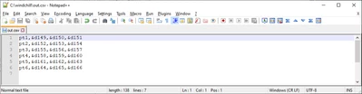
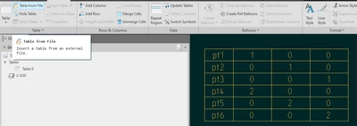
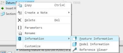
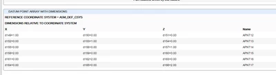
Not automatically, AFAIK, but if you do "feature information" on your point array feature, then you can copy the table text and parse it into excel or something like notepad++ and quickly generate the .csv file that can be brought into the drawing as a table:


pausob_4-1687755300740.png


-->


pausob_1-1687755165607.png

-->

pausob_2-1687755211675.png


-->

pausob_3-1687755262922.png


4 replies

Jun 25, 2023 7:50 PM UTC

Yes. The datum point feature creates dimensions for each point within the feature. In your drawing table add the dimension symbols as needed to the table and they will update with the model changes when applicable.


You can see here an example of the dimensions available when using a offset from Csys datum point feature. Each of these dimensions has a unique value and can be used in a table.


tbraxton_0-1687722549272.png


Jun 25, 2023 9:58 PM UTC

That is a good idea, thank you. Is it also possible to bring all dimensions as a table?

pausobAnswer
Jun 26, 2023 4:56 AM UTC

Not automatically, AFAIK, but if you do "feature information" on your point array feature, then you can copy the table text and parse it into excel or something like notepad++ and quickly generate the .csv file that can be brought into the drawing as a table:


pausob_4-1687755300740.png


-->


pausob_1-1687755165607.png

-->

pausob_2-1687755211675.png


-->

pausob_3-1687755262922.png